

Description
Wind Tower Girth Welder
Overview
As a core automated device for wind tower manufacturing, the wind tower girth welder is designed for high-precision circumferential seam welding of tower cylindrical sections.
With the global wind power industry developing toward large-scale and offshore, wind towers (80-160 meters now) have stricter structural requirements. Welds need superior strength, stability and corrosion resistance to withstand long-term wind loads, temperature fluctuations, and offshore salt spray/high humidity; their quality directly determines tower safety and service life, a key focus in wind power equipment manufacturing.
Traditional manual welding is a bottleneck: relying heavily on operator expertise, it causes inconsistent welds (defect rates often over 10%), low productivity and high labor costs.
Our automatic girth welder integrates advanced automation and precision control systems, solving these issues with uniform tower section rotation, consistent weld formation, stable and efficient production, less rework and lower labor costs, meeting industry quality and cost demands.
Compatible with mainstream high-strength low-alloy steels (S355J2, S355NL, Q420MC), it covers various tower diameters and wall thicknesses, suitable for both onshore and offshore wind power projects. Equipped with intelligent seam tracking and flux recovery systems, it ensures welding precision, reduces material waste and operational costs.
A leading European wind power equipment manufacturer achieved 40% higher efficiency, 97% fewer welding defects vs. manual welding, plus annual flux cost savings—tangible proof of its engineering value.
For detailed parameters or customized solutions, refer to the table below or contact us.
Automatic Girth Welding Process
To ensure the integrity and reliability of wind tower circumferential seams, our automatic girth welder standardizes the welding process into four sequential stages, minimizing human error through full-process automation.
Each stage complies with international welding standards, including EN 1090-2, ISO 15614-1, and AWS D1.1. Strict adherence to these stages is critical for avoiding welding defects in actual production—a fundamental principle of automated welding process design.
Welding Operation
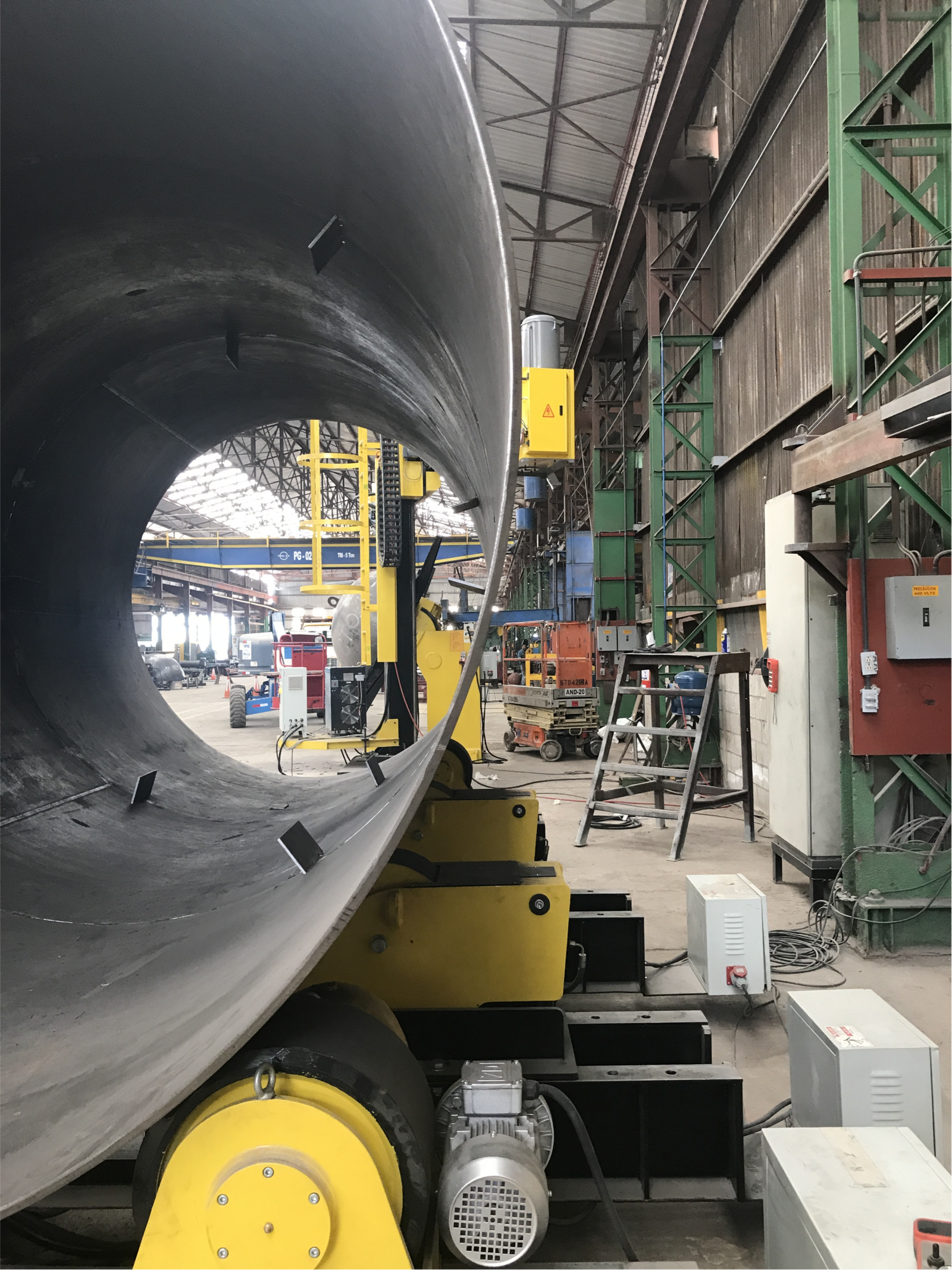
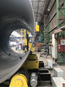
The welding head is positioned around the tower’s circumferential seam, with laser visual sensing technology ensuring precise alignment. Submerged Arc Welding (SAW) is used to maintain stable arc combustion and uniform weld penetration, while the tower section rotates at a continuously adjustable, steady speed.
- In a northern European onshore wind power project, 98 tower sections welded by this equipment achieved zero defects, all passing non-destructive testing (NDT). This demonstrates that stable equipment operation effectively guarantees consistent weld quality, meeting the technical requirements of wind tower manufacturing.
Pre-welding Preparation
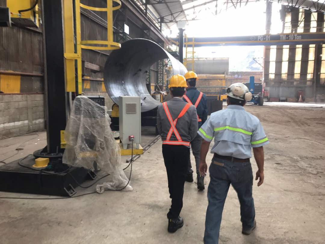
Two wind tower sections are hoisted onto a heavy-duty roller frame and aligned with an error of ≤±0.5mm to prevent misalignment defects. The welding bevel is cleaned via shot blasting to remove oxides, rust, and other contaminants—a critical step for avoiding porosity and incomplete fusion, common defects in welding engineering.
- In a North Sea offshore wind farm project, this preparation process reduced each tower section’s production cycle by 2 days and lowered material waste by 15%. Simply put, this step lays the foundation for high-quality welding; negligence at this stage will inevitably lead to subsequent welding defects.
Real-time Monitoring & Flux Recovery
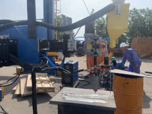
An intelligent control system continuously monitors key welding parameters—including voltage, current, and travel speed—making automatic adjustments to maintain consistent weld quality. This real-time monitoring mechanism is a core component of automated welding control systems.
- The integrated flux recovery system recycles 80% of unused flux, reducing material waste and operational costs. A German manufacturer reported significant cost savings after adopting this system, with reduced flux consumption and lower overall production costs—serving as a practical application of resource recycling in welding production.
Post-welding Finishing
After welding, the weld seam is cleaned to remove slag and spatter, then inspected via ultrasonic testing (UT) and magnetic particle testing (MT) to identify hidden defects like cracks and inclusions.
- The equipment consistently achieves a non-destructive testing pass rate of ≥99.5%, far exceeding the 95% industry average, thus ensuring long-term operational safety of wind towers. This final inspection serves as the last line of defense for weld reliability during long-term operation, an indispensable part of the quality assurance system in wind tower manufacturing.
Models & Specifications
We offer two specialized models (GT-GW-A and GT-GW-B), each customized to meet the diverse needs of onshore and offshore wind power projects. Both models feature industrial-grade components, including Siemens frequency conversion systems and Lincoln Electric SAW power supplies, ensuring durability, corrosion resistance, and stable operation in harsh manufacturing environments.
From a technical perspective, selecting industrial-grade components is crucial to the equipment’s long-term operational stability. A detailed parameter comparison is provided below to facilitate equipment selection, as model suitability directly impacts production efficiency and operational costs—a key consideration for enterprise equipment procurement.
GT-GW-A is suitable for small and medium-sized onshore wind towers, while GT-GW-B is designed for large offshore wind towers. The appropriate model can be selected based on tower diameter and wall thickness, providing a straightforward, efficient method for meeting production needs. This matching principle aligns with the technical characteristics of different wind tower manufacturing scenarios.
Seam Tracking & Flux Recovery
| Specification Item | Model GT-GW-A | Model GT-GW-B |
| Applicable Tower Diameter | φ3.2m – φ4.8m | φ4.6m – φ8.2m |
| Applicable Wall Thickness | 7.0mm – 65mm | 8.5mm – 85mm |
| Welding Method | Submerged Arc Welding (SAW) | Submerged Arc Welding (SAW) |
| Welding Power Supply | DC1050 + NA-4 | DC1250 + NA-4 |
| Wire Diameter | φ2.8mm – φ6.0mm | φ3.2mm – φ6.0mm |
| Welding Speed | 0.4m/min – 2.6m/min (continuously adjustable) | 0.25m/min – 2.1m/min (continuously adjustable) |
| Rotation Speed | 0.12r/min – 1.1r/min | 0.06r/min – 0.9r/min |
| Power Supply | 380V/50Hz, 3-phase AC | 380V/50Hz, 3-phase AC |
| Overall Dimensions (L×W×H) | 4600mm×1900mm×2300mm | 5300mm×2100mm×2600mm |
| Net Weight | 4000kg | 5500kg |
| Applicable Materials | Carbon steel, low alloy steel, S355N/NL | Carbon steel, low alloy steel, S355K2/S355NL, Q420MC |
Our wind tower girth welder gains core competitiveness from independent seam tracking and flux recovery systems, which govern welding accuracy, productivity and operating costs, and define the overall technical strength of automated welding solutions.
Tailored for wind tower fabrication, both systems maintain stable operation in harsh site conditions, setting our equipment apart from ordinary automatic welders and highlighting our technical edge.
Seam Tracking System
Combining laser vision and AI recognition, it collects high-precision 3D data of girth seams and auto-adjusts the welding head’s position and angle to eliminate offset defects. It enables full-circle tracking and adapts to various tower diameters and bevel styles with no manual operation required. Field proven: one European client cut weld misalignment defects from 7.5% to 0.15% and slashed correction time by 90%, delivering reliable precision and higher production efficiency.
Flux Recovery System
Fitted with a 250°C heat-resistant conveyor belt and high-efficiency vacuum suction, it recycles 80% of unused welding flux. It supports green production via material reuse, monitors flux levels in real time to avoid downtime, and uses detachable filters for easy upkeep. It effectively lowers material costs and environmental load, realizing eco-friendly, cost-effective sustainable welding production.
Applications
Our wind tower girth welder specializes in circumferential seam welding for wind tower segments, with robust adaptability for heavy-duty cylindrical structure fabrication across diverse industries.
It serves core production processes in wind power manufacturing and heavy engineering. Stable operation and premium build quality earn wide industry approval, backed by proven technical reliability and strong practical value.
- Onshore Wind Tower Production Suits 80–120m onshore wind towers with standard diameters and wall thicknesses, delivering steady weld quality and high productivity to replace inefficient, unstable manual welding.A European manufacturer upgraded to the GT-GW-A model, lifting annual tower section output from 550 to 1300 units with a 99.7% NDT pass rate and secured long-term global wind power partnership.
- Offshore Wind Tower ProductionFeaturing corrosion-resistant parts and sealed protection, it withstands salt spray, high humidity and other harsh offshore conditions for long-lasting, anti-corrosion welds.In a North Sea offshore project, the GT-GW-B model completed 85 tower sections. After 2.5 years of stable operation, no welding defects occurred, with efficiency 38% higher than manual work.
- Wind Tower Maintenance & RepairCompact and portable for on-site weld reinforcement and repairs, avoiding costly full segment replacement.It completed high-precision welding for 120 wind turbine brake caliper bases in narrow nacelle spaces in a European onshore wind farm, with all reinforced welds passing NDT fully.
- General Heavy-Duty FabricationVersatile for large cylindrical structure welding in petrochemical storage tanks, offshore platforms, pipelines and shipbuilding hull components.A European petrochemical plant adopted the GT-GW-B model for 6.0m-diameter, 55mm-thick tank welding, hitting 100% NDT qualification and 3.2 times higher efficiency than manual welding.

FAQs
Q1: What advantages does the automatic wind tower girth welder have compared to manual welding?
A1: Its core advantages include stable weld quality, high production efficiency, and low operational costs. From a technical comparison perspective, manual welding is prone to quality fluctuations due to operator skill differences. With a defect rate of ≥10%, while our automatic equipment reduces the defect rate to <0.5%.
Production efficiency is 3-5 times that of manual welding. And the flux recovery system cuts operational costs by 20-30%. These features effectively address the key challenges of manual welding. Inconsistent quality and low efficiency representing significant progress in wind tower welding technology.
Q2: Is the equipment compatible with different wind tower sizes and special materials?
A2: Yes. Our two models cover a diameter range of φ3.2m-φ8.2m and a wall thickness range of 7.0mm-85mm. Compatible with mainstream wind tower materials such as S355N/NL, S355K2, and Q420MC.
From the perspective of material compatibility and size adaptability. The equipment meets the technical requirements of most wind tower manufacturing scenarios. Customized services are also available for special needs. Such as ultra-large diameter offshore towers or special alloy materials. Ensuring a suitable solution for any wind tower size or material type—fully reflecting the equipment’s versatility and flexibility.
Q3: How to maintain the seam tracking and flux recovery systems to ensure stable operation?
A3: Regular maintenance is essential for stable system operation—a basic principle of equipment management in engineering practice. For the seam tracking system, clean the laser sensor weekly to avoid dust interference and calibrate tracking accuracy monthly.
For the flux recovery system, inspect the vacuum suction device weekly to prevent blockages, clean filters monthly, and refill flux promptly (a backup hopper is included for uninterrupted production). Adhering to this maintenance routine ensures a 99.5% long-term operational rate for the equipment, with straightforward steps supporting stable extended operation. Regular maintenance is the key to ensuring the equipment’s long-term stable performance.
Q4: What after-sales support is provided for the equipment?
A4: We provide comprehensive after-sales support, including on-site installation and commissioning, operator training, regular maintenance inspections, 24/7 technical support with a 4-hour response time, genuine spare part supply, and software upgrades.
From an after-sales service system perspective, this comprehensive support ensures enterprises can resolve operational issues promptly. On-site technical personnel are assigned to key projects for follow-up services. Ensuring timely resolution of any operational issues to minimize production disruptions. An important guarantee for the equipment’s stable operation in actual production.
Q5: How long does equipment installation and commissioning take?
A5: Installation and commissioning take 3-5 working days for standard models and 7-10 working days for customized models. This timeline is based on the equipment’s technical complexity and installation requirements.
On-site services are provided to avoid production downtime, with professional technicians. Completing installation and commissioning efficiently to minimize impacts on production schedules. This ensures enterprises can put the equipment into use as soon as possible, reducing disruptions to production progress.
UVP Module
Spec Sheet:
Download our detailed specification sheet for comprehensive technical parameters, dimensional drawings, component details. Real project case studies for both models. From a technical reference perspective, the specification sheet provides a comprehensive basis for enterprise equipment selection and technical research.
It facilitates quick model comparison, clarifies application scenarios, and supports informed equipment selection. Click here to download the Spec Sheet. It contains all details required for decision-making, eliminating guesswork—a convenient, practical technical reference tool for enterprises.
Process Diagram:
Our visual process diagram clearly outlines the full workflow of automatic girth welding. From pre-welding preparation and welding operation to real-time monitoring and post-welding finishing.
From an operational guidance perspective, girth welder process diagram plays an important role in standardizing the welding operation process. Click here to view the Process Diagram. Designed for ease of understanding, it enables operators to quickly master correct operational methods. Helping improve operational efficiency and reduce operational errors.
Reviews
There are no reviews yet.